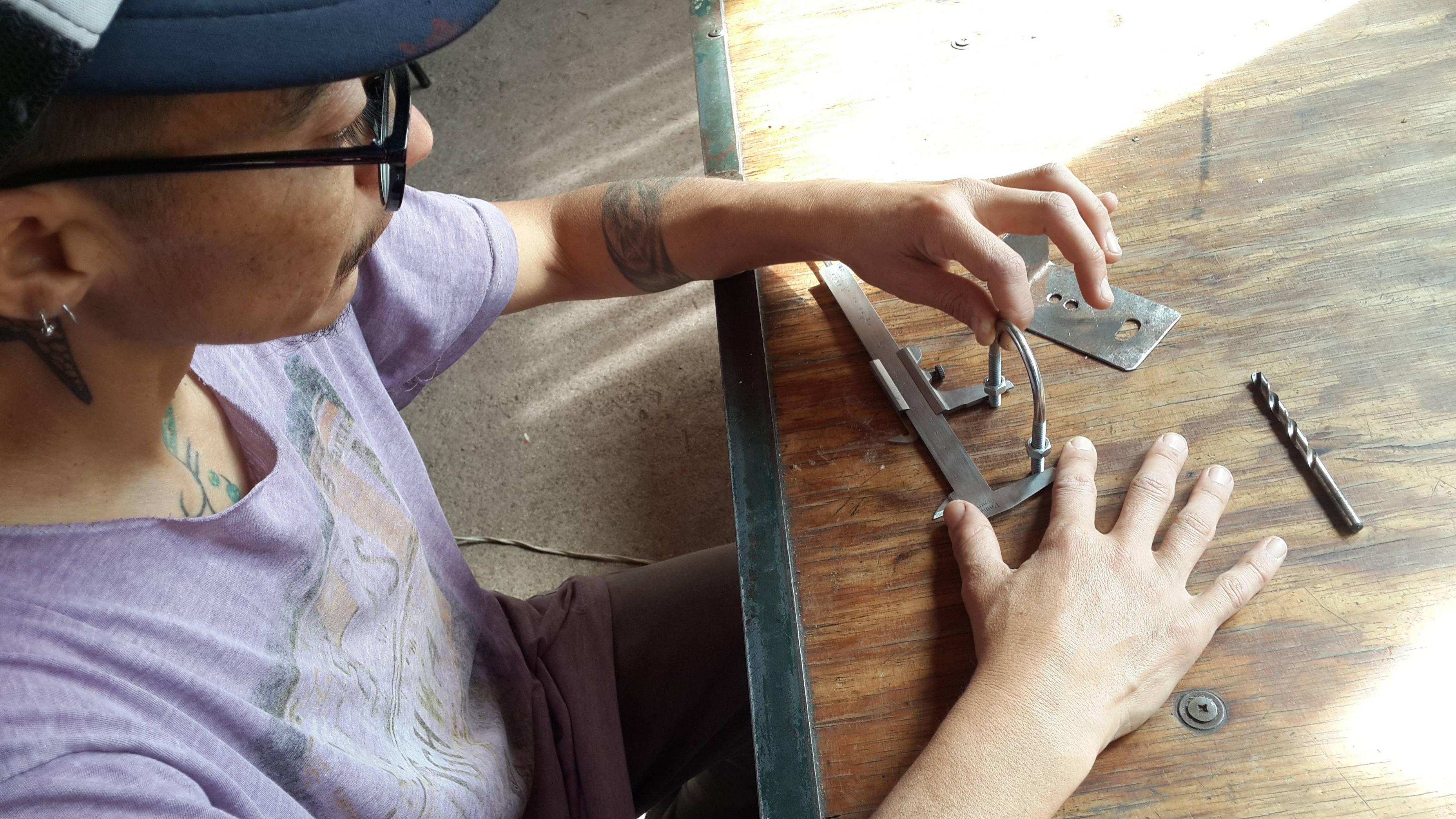
Prototyping
We will describe some characteristics of each antenna, and a graph of their tests performed with a program specially designed equipment for this purpose in a distance of 1.1 km. Our test scenario is located between a very tall pine tree in the town of Casa Grande and the top of a house in the town of Molinari.

Prototype 1
Version 1:
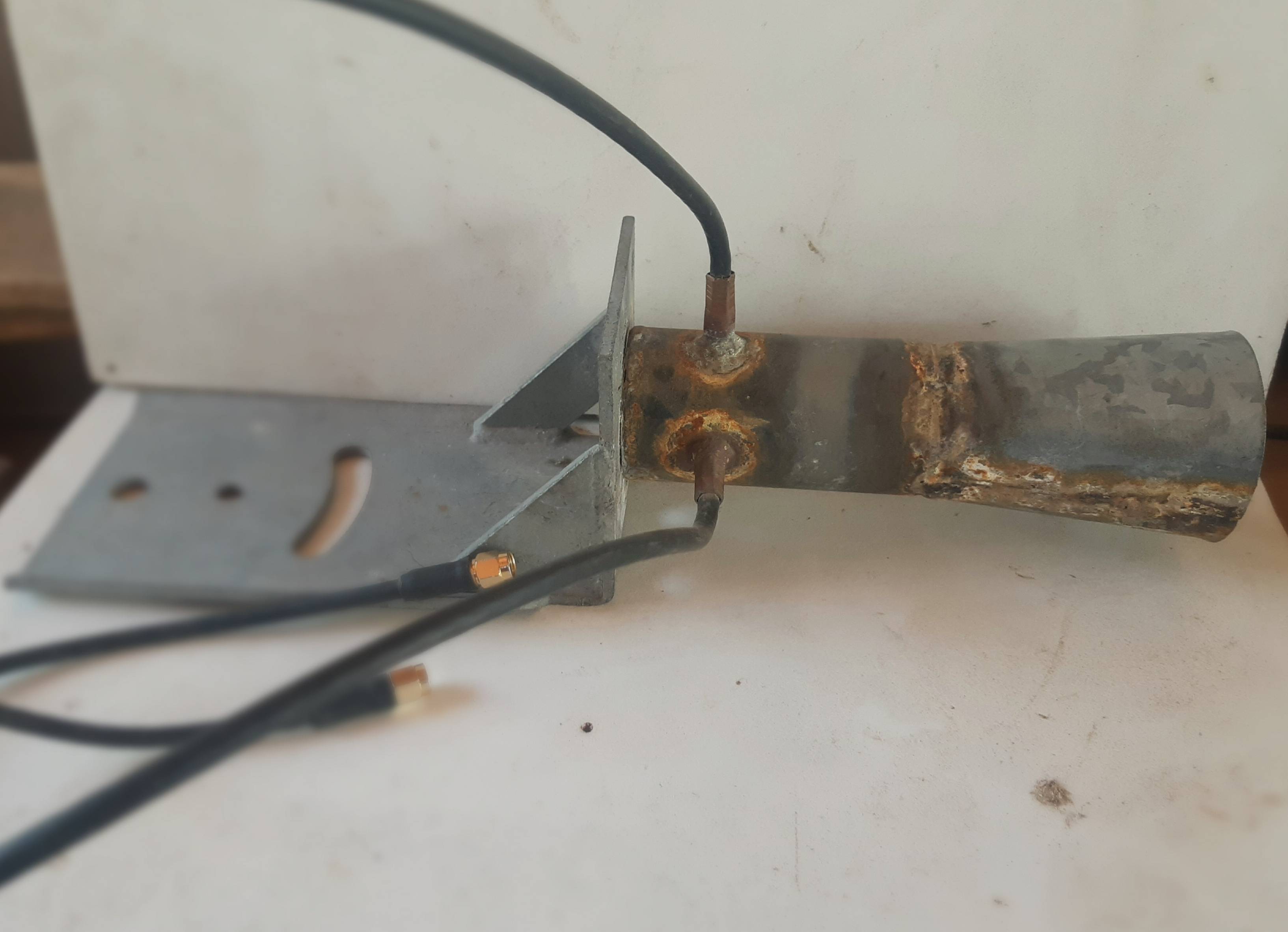
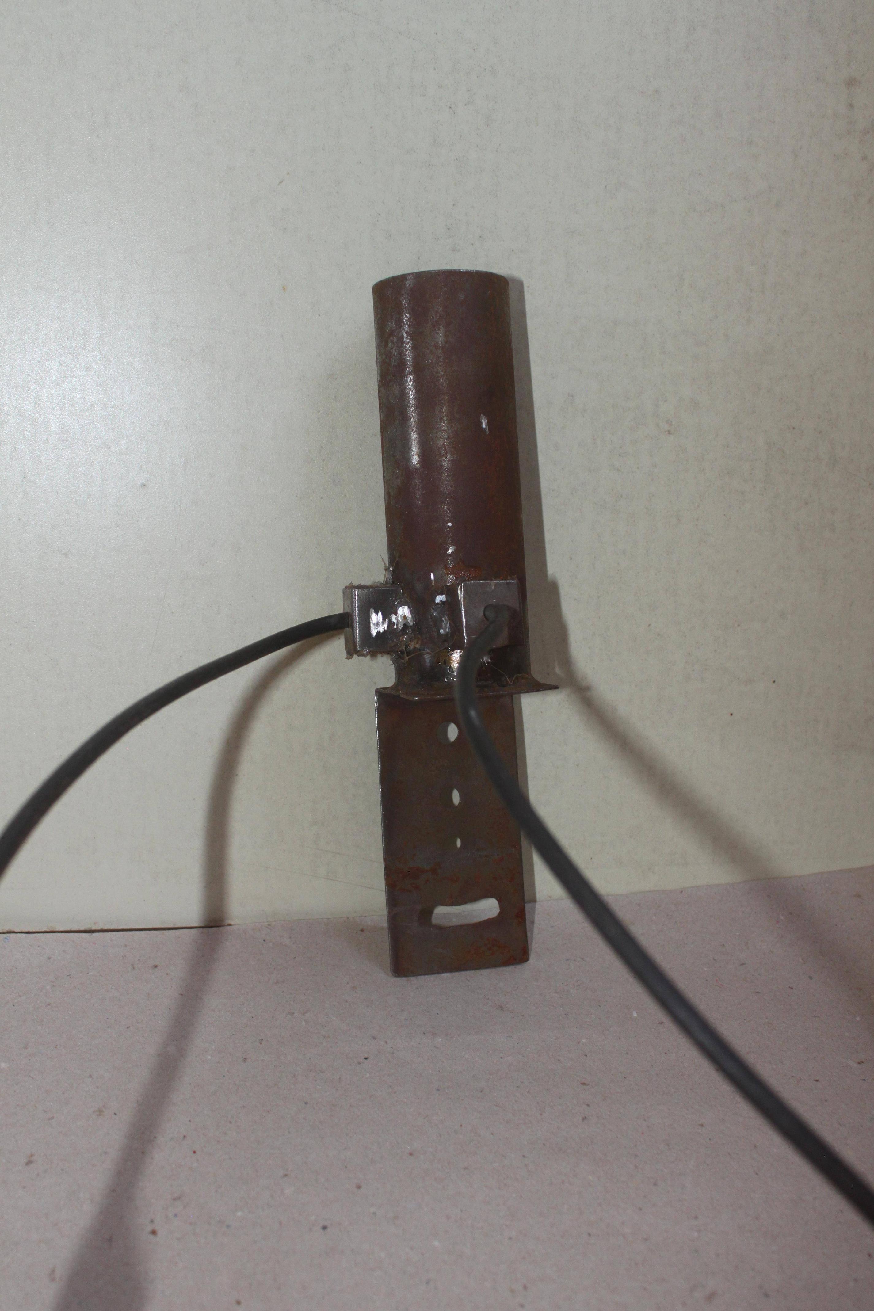
In the search for a waveguide type antenna, we developed this prototype; one of the aspects we worked on is the creation of a support for the antenna and the assembly of the cables on the waveguide.
An early attempt at support was this:
Taking an existing support, we welded the waveguide to it. In this case we use a 38mm diameter pipe.
- Advantages:
The way to hold the cables in this prototype was to make a groove in the waveguide and with that material, adding a copper pipe, hold the cable. This simplifies the assembly.
- Disadvantages:
Due to the characteristics of the material, its weight and its shape, we found this support design not very functional; this led us to rethink how to use the material and the shape of the support. The slot generates radiation loss. The diameter of the pipe "cuts" the passage of lower frequencies.
Version 2:
We tried modifying the length of the waveguide, with a longer pipe.
In this version, we modified the way of fastening the cables by soldering a copper pipe to the waveguide, crimping it, and sealing it with heat shrink.
- Advantages:
Robustness in the grip precision in the final position of the illuminators.
- Disadvantages:
We use an autogenous welder (oxygen and acetylene) which incre  ases the complexity of the workshop and the difficulty of welding. There is also the possibility of generating "joint stresses" between the materials, which could affect the performance of the antenna.
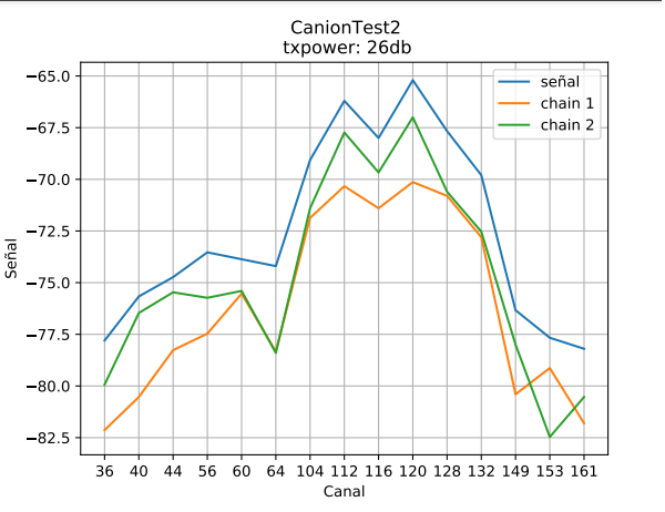
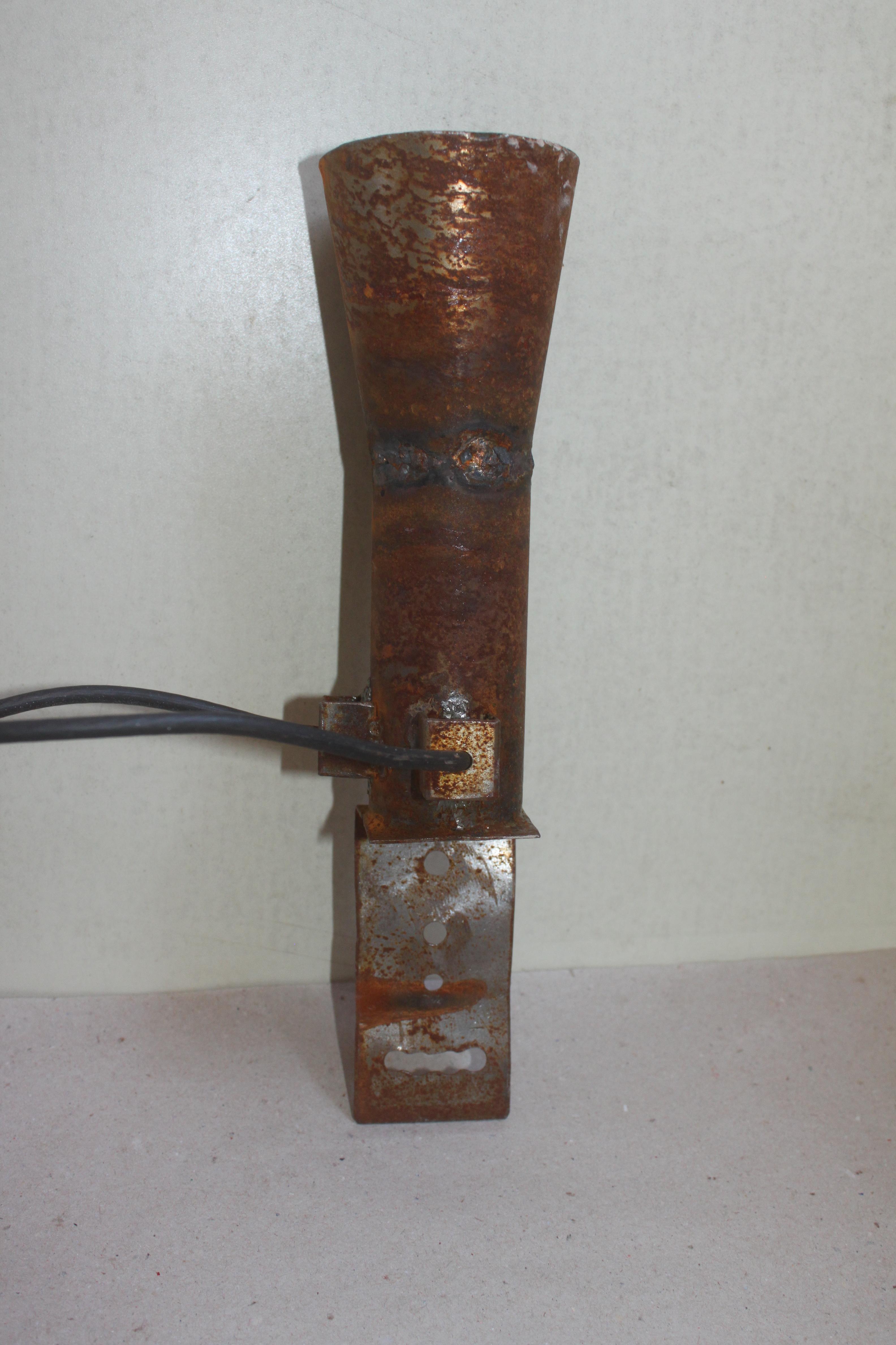
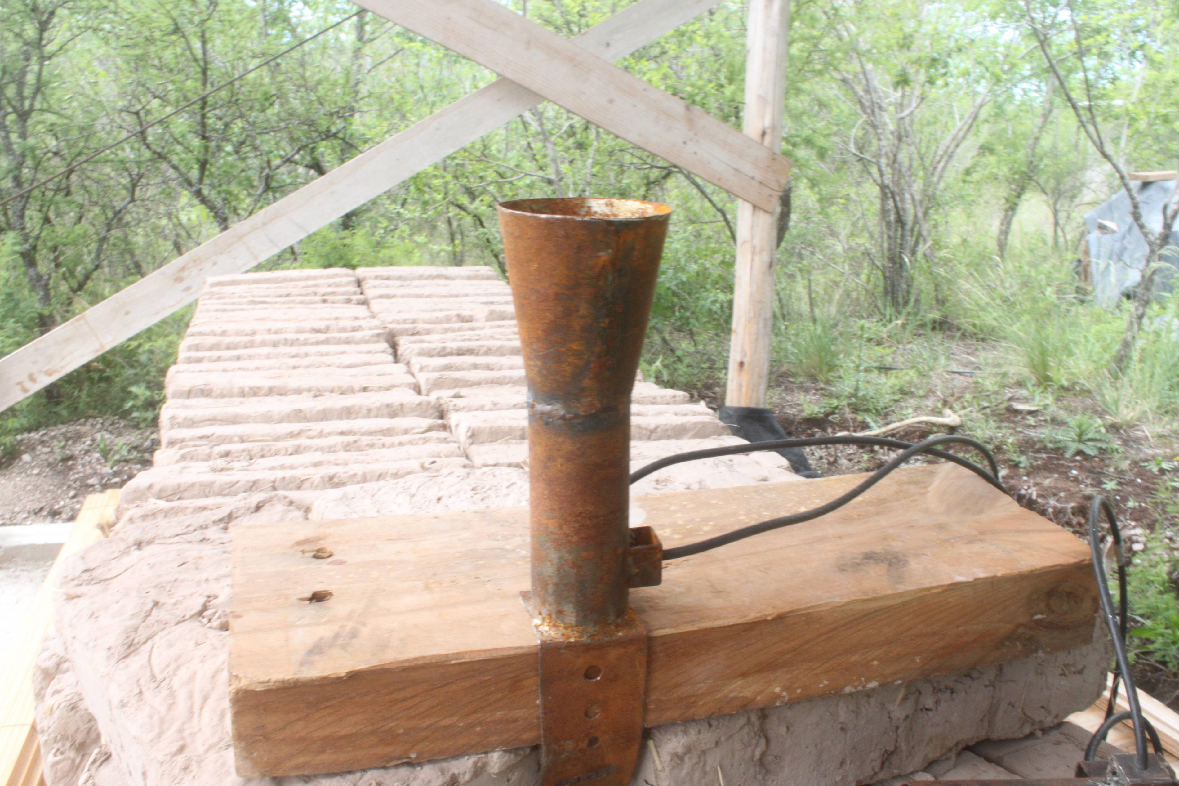
Prototype 2 Conical:
Version 1:
In this version, we reattached the cables as in the previous version, soldering a copper pipe to the waveguide, crimping it, and sealing it with heat shrink.
- Advantages:
We observed that the addition of the conical supplement improves its performance.
- Disadvantages:
For this prototype, we used the large bracket, which is very heavy. We consider it not very functional.
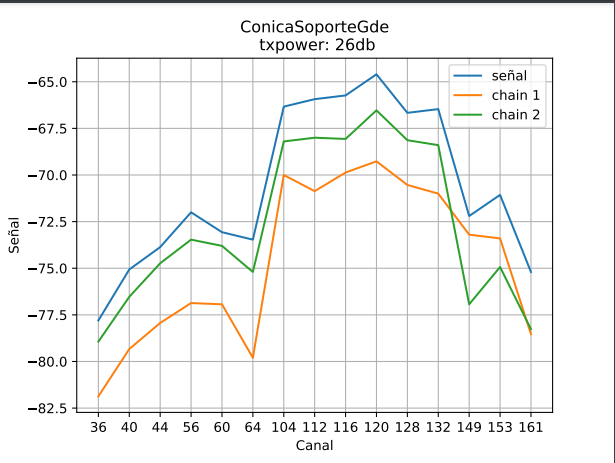
Version 2:
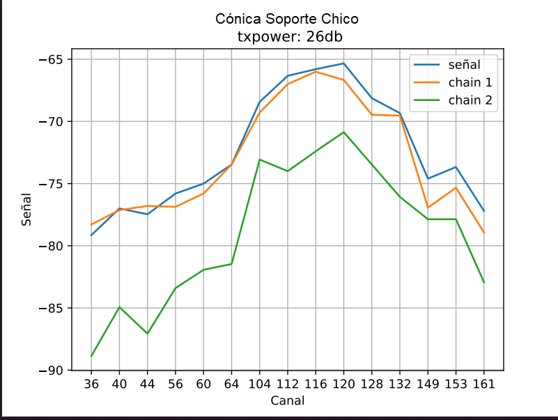
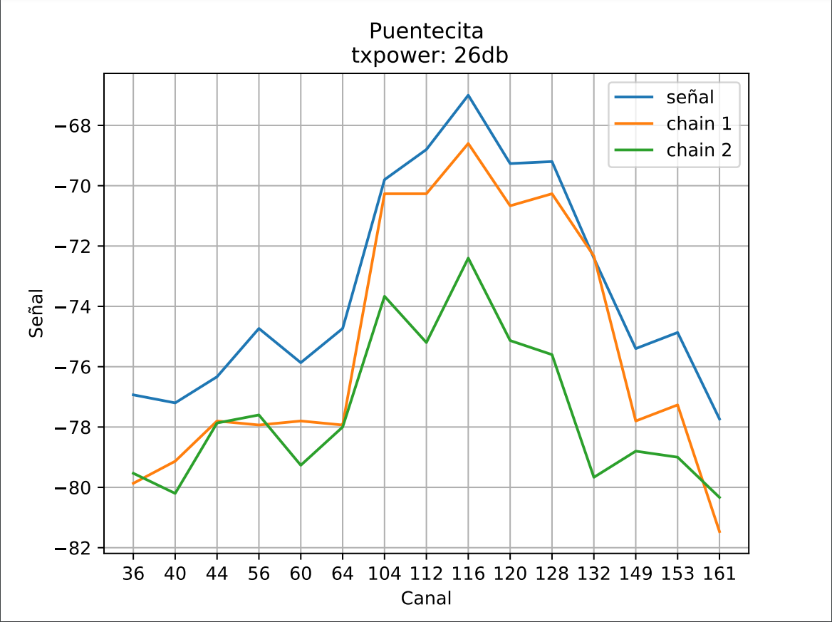
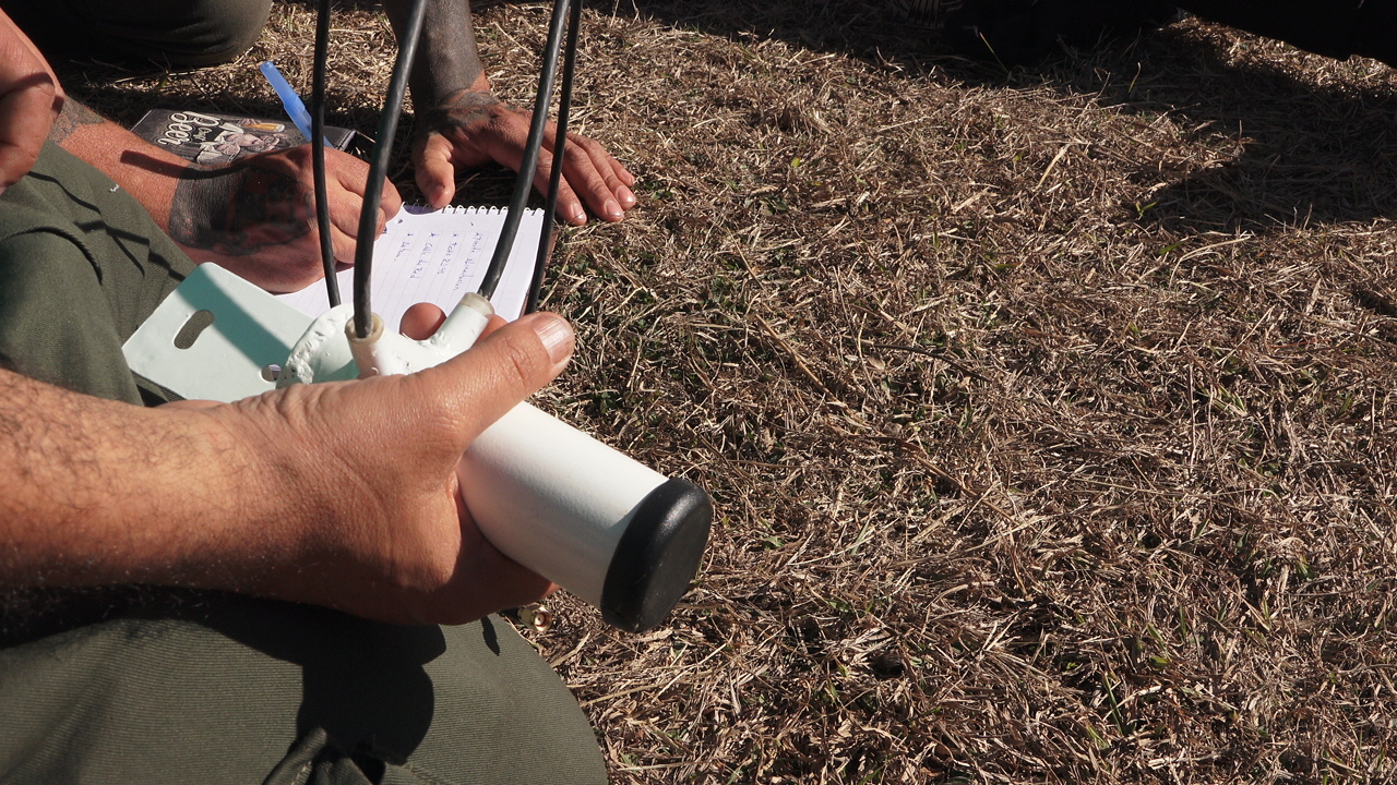
In this prototype, we shortened the length of the pipe, with an internal diameter of 42 mm, adding a conical end made of sheet metal and welded. To support the cables, we designed a "bridge" type grip with sheet metal welded to the waveguide.
- Advantages:
In relation to the support, being lighter and more compact, it allows to move it more easily, being also more economical because it has less material. In this version of the support, we drilled holes to take advantage of the measures of the "threaded u" that are easily available in hardware stores, creating a support adaptable to two sizes of pipe. This provides accessibility to the product.
With this design, we are using the bracket as the waveguide cover. The first prototype of the bracket welded as the antenna cover was 10 cm long. Then we chose to leave room for only two sizes of "threaded u", thus giving the possibility to complete the bracket according to the pipe where it is attached.
- Disadvantages:
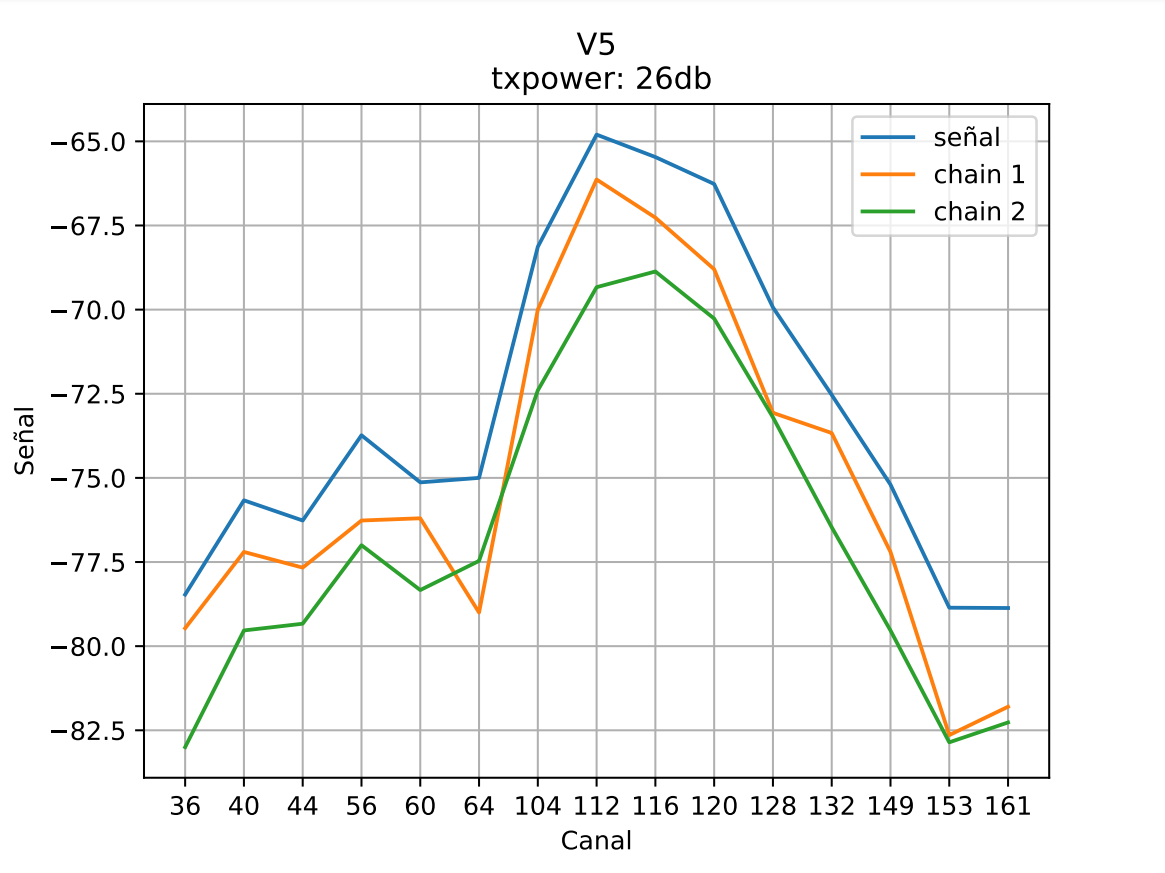
In this prototype, we found many difficulties in soldering the wires to the waveguide. It can be seen in the measurement graph as chain 2 (the green one) with failures in the soldering of the mesh, has lower gain.

Prototype 3
In this version, we retested attaching the wires with the bent sheet metal "bridge" model, on a shorter waveguide prototype, with 44mm internal diameter, without a cone.

Although we obtained very good results in antenna performance, we are still looking for a simpler way to attach the wires, preserving the length of the waveguide in the next prototype.
- Advantages:
We obtained good performance results.
- Disadvantages:
Difficulty in soldering the wire mesh to the pipe
Prototype 4 Resin
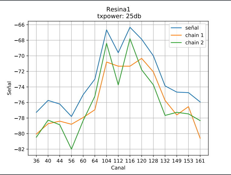
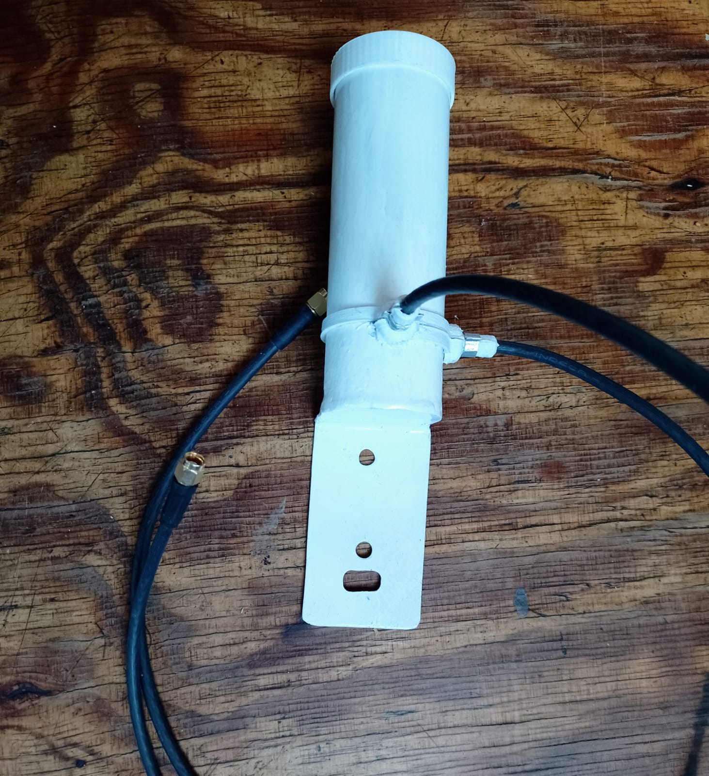
In this prototype, we tested attaching the cables with a ø=1/8 inch hose, transparent, filled with epoxy resin.
- Advantages:
Antenna performance results were good.
- Disadvantages:
Fragility at the junction of the cables with the waveguide. Some tests came unglued, making them unusable. Difficulty in removing resin residues in case of need for repair. Toxicity of the process and the resulting residues.
Prototype 5 Coupling of plastic parts
Through the design in Freecad, we were able to 3d print plastic parts that allow, by coupling, to hold the cables in an efficient, fast and durable way.
- Advantages:
Simple assembly. Robustness and precision in cable gripping.
- Disadvantages:
Access to 3D printing. Need to develop waterproofing at the junction of the plastic parts.


This project was funded through the User-Operated Internet fund, a fund established by NLnet made possible by financial support from the PKT Community The Network Steward and stichting Technology Commons Trust.
Saludamos a les amigues de AlterMundi.